
Description
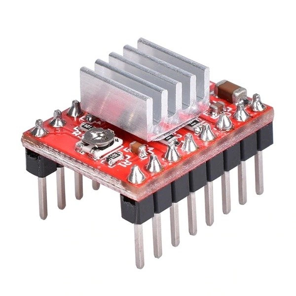
A4988 module – stepper motor controller
A4988 Stepstick motor driver module is a stepper motor driver with up to 2A current per coil and a wide supply voltage range from 8V to 35V.
Circuit commonly used in CNC machines and 3D printers (RepRap) and others.
Product features
- A4988 Stepstick motor driver module heatsink included
- Controller ideal for 3D printers (RepRap)
- Examples of use in CNC Shield for 3D Printers
- Stepper motor controller based on the A4988 chip.
- Wide range of supply voltage 8 – 35 V
- Large operating current of up to 2 A per coil.
- Maximum resolution: 1/16 step.
- Note! Connecting and disconnecting the motor while the controller is on can damage the system.
Technical data
- Module equipped with A4988 chip
- Motor supply voltage: 8-35 V
- Max current: 2A with heat sink
- Operation in 5 different modes: full step, 1/2, 1/4, 1/8 and 1/16 step
- Possibility to adjust the current drawn by the motor with a potentiometer – ceramic screwdriver available here.
- Protection against overheating of the system
Included
- Stepper motor controller module A4988
- Radiator
Important information
- Wiki to A4988
- Reprap – driver description
- Controller data sheet
Detailed description of the controller
- Control
- The module is characterized by very simple operation.
- In order to rotate the motor by a step, a high state (logical one) must be given to the STEP lead, the next sequence of zero and one will move the motor by the next step, etc.
- Selection of the direction is carried out by applying the appropriate state to the DIR pin (e.g., low state – clockwise rotation, low state – counterclockwise).
- The controller also has a selectable motor resolution.
- Power supply
- To power the logic part of the module, a voltage in the range of 3V to 5.5V is required, which should be applied to the VDD pin.
- The motor supply voltage from 8V to 35V is applied to the VMOT pin. The system can be used to control motors with a nominal voltage lower than the required 8V. To do this, limit the maximum current draw using a potentiometer so as not to exceed the allowable motor current. E.g. for a motor with a resistance of 5Ω per coil and current consumption of 1A, the nominal supply voltage is 5V. When supplying 12V, limit the current so that it does not exceed 1A.
- Other inputs
- One pulse applied to the STEP pin causes one motor step in the direction selected by applying the corresponding logic state to the DIR pin.
- STEP and DIR outputs are not internally pulled up.
- If the motor is to spin in one direction only, the DIR pin can be permanently connected to VCC or GND.
- The circuit has three more inputs to control power consumption: RESET SLP and EN their description can be found in the documentation.
- Note that the RESET pin is not connected to anything. When not in use it can be plugged into the adjacent SLEEP pin.
- Current limitation
- A4988 module allows active current limitation using a potentiometer.
- One way to implement the limitation is to set the controller to full step mode and measure the current flowing through one coil without applying a signal to the STEP input.
- Measured current is 70% of the set limit (both coils are always on and limited to 70% in full step mode).
- Another way is to measure the voltage at the REF lead (marked with a circle on the PCB) and calculate the current limit (the measurement resistors have a value of 0.05Ω).
- For more details, see the A4988 chip documentation.
- Heat dissipation:
- The board is designed to be able to dissipate heat at a current consumption of about 1A per coil.
- If the current will be much higher, it is necessary to use an external heat sink for the installation of which you can use thermally conductive glue – heat sink in our offer

Reviews
There are no reviews yet.